Category Archives: Skoolie

Electrics (Part I)

After the air system was in, and I knew the locations of the air lines and accouterments, I could run the electrical lines.  A good friend of ours had let us salvage parts from a 1970’s vintage RV trailer, and from that I was able to get some electrical components,   the two important ones for this were the 10 gauge 25′ power cord and the 30 amp circuit breaker box.  The box had a 30 amp main switch, and three additional 20 amp breakers.  The only odd thing was that the 30 amp plug

A 30 Amp plug

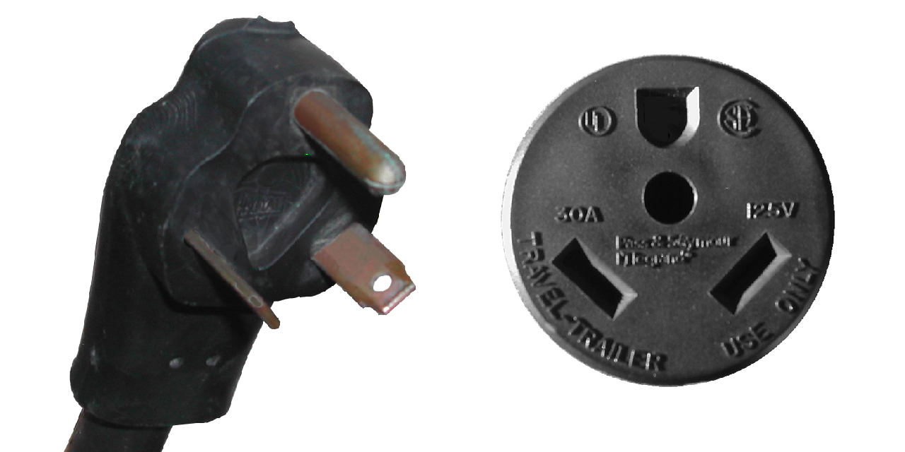
on the end of the power cord had been replaced with a 15/20 amp plug meaning that the power coming into the bus was limited to 20 amps (so far).

15/20 Amp plug

One of the critical things that I learned on our Sprague Brook trip is that getting the power inside the bus proper is very important.  And having a roll of 25′ of three-ply 10 gauge stranded wire to connect to a power outlet outside the bus is no small thing to mount in a secure location.

I decided that the wire would coil in the empty area of the battery box on the port side of the bus, and thus would have to come up through the floor just by the heater box inside the bus compartment (right by the captain’s chair).  As with the soft air line, this needed to be protected from the sharp edge of the metal floor, where the vibration and movement of the floor while the bus is in motion could cut the insulation and wires, producing a dangerous short or a ‘hot skin’ condition of the bus, which is where the metal skin and frame carry the 120 volt AC current, and anyone touching it completes the circuit (Zap!).

I wanted to keep the 10 gauge wire, though, as the smaller the gauge, the less electrical energy is lost getting from the plug to the outlet, and it turned out that the ~1/2″ cable fit just inside a 3/4″ compression connector (for an electrical box to connect to a rigid chase pipe) that I had acquired as a “bit”.  once I had double checked that the hole I was going to drill would come out in the battery box, I slid the compression connector down into the hole and screwed it down tight (leaving the unneeded compression fitting off), and it produced a perfect safety barrier against the sheet metal flooring.

Looking into the battery box, the connector is on the top and the cable coming down through the floor.

After the connector was fitted, I ran the wire through it, attached a new 15/20 amp plug, and then set up the breaker box.  I decided to put it just behind the captain’s chair, as it wouldn’t be of any use while the bus was in motion, and was conveniently located by the battery box and the seat where I would be storing the house batteries.

The breaker box in place in the frame of the wall between the captain's chair and the rear-facing bench seat in the passenger area.
The breaker box in place in the frame of the wall between the captain’s chair and the rear-facing bench seat in the passenger area.

The box has a 30 amp main, and three 20 amp feed breakers.  I attached the power cable to the main, and ran one of the 20 amp breakers to outlets behind the captain’s chair and another in the ‘closet’ area behind the wet-wall for the bathroom.

The specs on the power converter.

Another of the breakers was dedicated to a Magnatek Model 3240 power converter.  This is a unit that takes 120 volt AC  input and converts it to 12 volt DC current.  it can be hooked up to 12 volt batteries and has an automatic switch to detect the AC power, and switch to battery power when the AC is disconnected, and vice versa, without cutting power to the attached 12 volt appliances.

The power converter in place behind the rear-facing bench seat, attached and double-grounded against the wall.

I had picked this up when I got our fridge (a forthcoming post) and the guy threw it in for a very small amount, which on the one hand is great, since we needed something like this, and on the other hand is annoying, since it was an ‘as is’ purchase and it turned out the battery charging element wasn’t working.    At any rate, the converter is a simple affair, using regular automotive ‘knife-style’ fuses, and having both filtered and unfiltered DC outputs (filtered is for sensitive electronics, like the radio).  One of these I set up to go to the radio/tape deck, so that the clock would stay running and I could listen to music while the bus wasn’t on, and another I would run off to the DC connection for the fridge.  Others would be for lighting and appliances like the water pump and water heater, but those will come later and be run through a DC breaker box which isn’t in place yet.

More on this in Electrics (Part II)


Air (Part III – The SuperTyfon)

The other sounding unit was the air horn.  This was a massive cast aluminum fixture with three bells of varying lengths, producing three different notes.  While several of the Leslie horns produced nice chords, the combination of horns chosen for the Conrail locomotives in the 1970’s produced a more discordant sound, likely to attract more attention.  The Leslie SuperTyfon RS-3L is one of them, the horns producing the C, D#, and A notes.

The ‘S’ is for the SuperTyfon style of horns, the ‘R’ is for the the spike-backed chamber, which helped to make the horns more dependable and durable, the “3” indicates that the horn has three bells on the manfold, and the “L” indicates that the three bell combination for this horn is bells 25, 31, and 44 (C, D#, and A, respectively).  Given that the spike-backed chambers were released in 1977, and the ones on this horn indicate that they are amongst the earliest runs or production, I’m guessing a late 1970’s-very early 1980’s construction for this horn.

The Supertyfon horn, still with the Conrail blue on it.
The SuperTyfon horn, still with the Conrail blue on it.

When I got it from my father, it still retained some of the ‘Conrail blue’ paint, but so much was worn away that it looked rather shabby.

My make-shift blasting box is basically a tarp and card table - important to collect the media, both for re-use and to keep it from going everywhere!
My make-shift blasting box is basically a tarp and card table – important to collect the media, both for re-use and to keep it from going everywhere!

I decided to clean and repaint it, and started with a sand-blasting with the black diamond grit in my little air blaster.

Post-blasting, the horns are a nice, clean aluminum.

The end result was really nice clean aluminum, and actually exposed the original plate manufacturer’s plate that had been painted over.

Since I was repainting it, I decided to be a little fancier than just giving it one color, deciding on a gloss bright red for the bell interiors and rims, and a gloss black for the rest of the unit.  This went pretty well, with only a little crackling of the black paint where it went over the red, but I sanded this and put more coats of black on and minimized it considerably.

The red paint is already on, and the tape is on so I can spray the black on and leave the red rims.


Spraying the black paint on the horns.  The tape is holding plastic bags that will keep the insides red.
Spraying the black paint on the horns. The tape is holding plastic bags that will keep the insides red.


Installation here, though was more complex than for the chime, due to the fact that the horn had to be mounted up on the roof behind the first support, which meant that it would be under the metal ceiling and need a 90 degree barb fixture that would have to be put in place before the four bolts holding the manifold down could be put in place.  Luckily, I was able to ply a friend with some homebrew and have him stand on the hood of the bus, holding the horn and wrenches in place while I worked from inside to secure things.

(This may sound like I was taking the easier job, but realize that only the front edge of the metal ceiling was loose and the area between it and the roof was full of yellow fiberglass insulation that the ceiling plate kept pushing up while I was trying to work in there.  Plenty itchy work.)

Each of the four bolt-holes, as well as the air-line fixture were surrounded with the butyl around each of the holes.  Once the barb fitting was in place, the stainless-steel bolts were fixed with a lock-washer and nut and cinched down.  The soft air line was run to the horn, and after starting the bus and building pressure in the tank, I gave a very brief voicing of the chimes and the horns, so as not to annoy the neighbors.

Here's the horn in place, all secured and hooked up inside.

Here’s the horn in place, all secured and hooked up inside.

Everything worked nicely, though I found a small leak in the hardline for the chime, so I popped off the soft line, moved the line so that I could remove the pipe from the leaking fitting, replace the Teflon tape on the threads and put it all back together.  As of right now, it is working well and holding pressure as it should.

Both the chimes and the horns in place and ready to go.


Air (Part II)

Now, to run this from the tank below the floor up through the bus body and out to the horns needed some other bits to work correctly.  First was to put in a pressure regulator, which by adjusting the dial could throttle the pressure to any desired between zero and 200 psi, or however much was in the system.

Pressure Regulator
Pressure Regulator

This was an important consideration that many of the ‘air horn kits’ that I found on-line lacked, as it allows you to quiet your air horns/chimes while you’re in an area with people out and about, rather than a highway with people in vehicles.  While there are people who seem to delight in scaring people with a sudden blast of sound from an air horn at maximum pressure, this is horribly irresponsible and potentially dangerous.

As the regulator had not only a 1/2“ through port, but also two 1/4“ regulated out ports, I decided to use one of these to run to a pressure gauge that I could mount on the control panel.  For this I used mainly a ‘soft’ line of a tough plastic with a 3/8“ interior dimension (but was marketed as a 1/2“ air line), which was not great at turning corners, kinking easily, and causing me to use hard 90 degree elbows to make corners.  This was a great way to check what the pressure is in the auxiliary tank, but had the drawback in that when you dial back the regulator to quiet the horn/chime, you only see the regulated pressure, not the whole tank pressure.  However, as the regulator dial is mounted behind the driver’s seat, this regulated gauge allows you to change the pressure without looking back for too long while driving.  The gauge itself had threads that were just the size of a removed switch cap on the control panel, so the installation was relatively easy, despite having to route the line between all the other lights and switches on the panel.

'Soft' air lines, 1/2" ID in the box and the 3/8" ID around the outside ...
‘Soft’ air lines, 1/2″ ID in the box and the 3/8″ ID around the outside …

The next step after this was to install control valves to actually work the horns.  While some people on-line suggested using simple ball valves for natural gas/LP lines, these don’t automatically close, which poses an additional distraction while driving, as opposed to spring-loaded, normally closed valves.  I got two non-stepped valves, which are amazingly heavy-duty.  Stepped valves have three settings (closed, partly open, and full open), while non-stepped run from closed to full open and all the range in-between depending on how hard you pull on the handle.

Non-stepped control valves

To counter the possible torque of pulling on one of the handles energetically during a tense moment, I ended up deciding to use hard lines from the regulator to the valves, which made things a bit easier as I needed to split the air line to get to both of the valves.

The lines for the air horns was 1/2” (ID) line to supply the volume of air needed to sound the horn, which can drain the 20 gallon tank fairly quickly, and the hard line was constructed from ‘black’ pipe and brass fittings, and used Teflon tape to seal the threads.

Showing the hard lines from the pressure regulator to the valves mounted on the shelf to the port side of the captain's chair.
Showing the hard lines from the pressure regulator to the valves mounted on the shelf to the port side of the captain’s chair.

These were attached to the shelf that I ended up constructing just above the captain’s chair on the port side, giving easy access to the valve handles, while also not blocking the view.  I had expected to put a couple of hanging lines on the handles (like the old truckers had), but the valves ended up being so low and handy that I decided against it.

Another view of the hard lines and valves without so much backlighting.

While I went with hard lines from the pressure regulator to the valves, most all of the rest of the line was ‘soft’, a thick, durable air brake line of woven fiber and rubber that could be bent into tight angles without crimping or binding.  This allowed for some flexibility of where to run the lines and to easily get the air to a horn along the curved roof.  However, it did pose one problem; that of how to run the soft line through the flooring, which was a 20 gauge steel sheet.

The nice bright dot (of the bright driveway) is  where the air line will come up
The nice bright dot (of the bright driveway) is where the air line will come up

I got around this by using a short ‘hard’ pipe through the floor with flared barbs at each end to attach the pipe and the ‘soft’ line.

A brass barb fitting on a black iron pipe to go through the floor


A dark photo of the connection between the tank and the 'through-the-floor' fitting
A dark photo of the connection between the tank and the ‘through-the-floor’ fitting

The first air sounding unit I put in was the air chime.  Nicely finished with brass, I wanted to install it with the pipes pointing up, but due to the construction of the lower ‘bell’ housing not having any drainage hole for rainwater, if I had, the air line down to the valve would fill with water and a winter freeze would have been disastrous.  So, it got mounted sideways, which still isn’t bad.  I ran the holes through one of the plates that I put over the school bus flashers, and piped a hard, brass air line in through the steel.  The mounting for this was simple, as the chime had three threaded holes to secure it, so once the exterior of the holes had been ringed with butyl sealant, it went together easily and securely.

4 Note Air Chime, Brass (From raneystruckparts.com)

That said, a word of advice to people who might be considering doing something like this – be careful with your bolts after getting things in place.  The butyl sticks to everything, including bolt threads, and can make it tough to get things aligned.

But it certainly can be worth it, as shown by the finished chime, in place:

The air chime in place above the driver's eyebrow
The air chime in place above the driver’s eyebrow

To be continued (in Part III) …