Tag Archives: School Bus RV

Electrics (Part II)

(Continued from Electrics (Part I))

The next step was the batteries. Of course, the bus already had two big batteries wired up to start the bus, so you might ask why we’d need other batteries. The answer is that there are two types of batteries that you’d find in an RV (or maybe even your car), and they each do different jobs.

The batteries already in the bus, and the ones in regular cars, are primarily meant to start the car and store up excess power from the alternator. That is, they are meant to have a high/hard draw of electricity in relatively short bursts. Often these will have ratings of ‘cranking’ amps or ‘cold cranking’ amps to show how much ‘power’ they have compared to other such batteries. Bigger batteries have more ‘cranking’ amps, meaning that they can provide more power to the starter. The bus’ two batteries have a total of 1880 ‘cranking’ amps and 1500 ‘cold cranking amps’. (For a comparison, my pick-up truck has 825 ‘cranking’ amps and 690 ‘cold cranking’ amps.)


The type of batteries that I added were ‘deep cycle’ batteries, which are meant to be slowly discharged of more power than the regular auto batteries are.  Thee are rated in ‘amp hours’ which tell you how long they will hold up giving power dependent on how much draw you put on them.

You might be wondering how you would know if you have a battery with enough ‘amp hours’ for your system.  There are a number of different on-line calculators (here’s one from http://www.batterysizingcalculator.com/ ) to make sure you get what you need.  Many RV systems are set up for only 20-24 hours of battery usage, assuming that you’ll be running your generator, plugging into shore power, or be using your vehicle’s alternator to recharge your batteries by then so you don’t overdraw your system.  A system that draws 30-40% of your battery’s ‘amp hours’ in 24 hours will totally drain your batteries in three days of use!  (A great resource on understanding all this is in “RV ELECTRICAL SYSTEMS-A Basic Guide to Troubleshooting, Repair and Improvement” by Bill and Jan Moeller, 1994, Ragged Mountain Press, Camden, ME  which is a little outdated on some of the appliances available but the theories and math are really sound.)

Anyhow, I worked out our system for four days of off-grid usage, estimating for a bunch of appliances and hour-usages, and came up with about 480 amp-hours at 12 volts that we needed.  There are a number of ways to get that.  Some people use a number of smaller voltage batteries (6 volt golf cart batteries are favorites) that can be wired in series to give the 12 volt systems, or several 12 volt batteries wired parallel to give the amp-hours needed, or combinations of series and parallel connections of lower voltage batteries to give the right voltage/amp-hour combinations.  The trick in all these is to use the same type/capacity batteries throughout the system, or the batteries could be damaged through uneven power draw or charging.

Another consideration was which type of battery to choose.  Most car batteries are flooded or wet-cell, which can be ‘sealed’/’maintenance free’ or  ‘serviceable’; the ‘serviceable’ ones being the ones you have to top up with distilled water and have to be sure to give adequate venting to let off the (potentially explosive) hydrogen gas and the sulfuric fumes that can come from charging, while the ‘sealed’ ones have the ‘eye’ that give you a color if everything’s okay, but can still vent gasses while charging.  These have to be mounted upright (or they could spill), and need to be mounted outside of the ‘liviing’ area of the vehicle (or be really well vented in a non-reactive compartment).

Additionally, there are AGM (Absorbed Glass Matt) and Gel-Cell are different in that the electrolyte isn’t simply in a liquid, but rather in a gel held between the plates in the battery, with the Gel-Cell actually being more of a rigid gel with a higher silica content.  These can be mounted in any direction and only off gas is badly overcharged (or with the wrong charger in the case of Gel-Cells), so these can be mounted in a passenger compartment without special ventilation.  The AGMs are considered one of the best at holding charges, and the Gel-Cells are considered very deep cycle (with a very slow recharge time) and have better durability in hot weather.  (Nice info summary and more info here at http://www.batterystuff.com.)

I ended up going with two Lifeline GPL-8DL batteries, each 12 volts with 255 amp-hours, so that when run in parallel we would end up with 510 amp-hours.  These are, however, pretty sizable batteries, each weighing 162 lbs, and being 20″ x 11″ x 9 3/4″ in size.   As big as this is, though, the two of them fit just fine under the rear-facing bench seat behind the captain’s chair, which serves to keep the length of 2-0 line running from them to the convertor (and later to the inverter and solar controller) to a minimum.

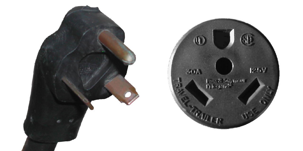
To be safe, I wanted to put a fuse in the system, and found a 500 amp surge/125 amp continuous fuse, with a little 15 amp bypass fuse that  would keep small systems running after the big fuse burned out.  In addition, the big fuse could be unscrewed to limit the danger to the batteries themselves.  When you are working with so many amps, even at a seemingly harmless 12 volts, it can be dangerous.

Now, I needed to put in some appliances! (Or at least one …)

Continued in Electrics (Part III)

Electrics (Part I)

After the air system was in, and I knew the locations of the air lines and accouterments, I could run the electrical lines.  A good friend of ours had let us salvage parts from a 1970’s vintage RV trailer, and from that I was able to get some electrical components,   the two important ones for this were the 10 gauge 25′ power cord and the 30 amp circuit breaker box.  The box had a 30 amp main switch, and three additional 20 amp breakers.  The only odd thing was that the 30 amp plug

A 30 Amp plug

on the end of the power cord had been replaced with a 15/20 amp plug meaning that the power coming into the bus was limited to 20 amps (so far).

15/20 Amp plug

One of the critical things that I learned on our Sprague Brook trip is that getting the power inside the bus proper is very important.  And having a roll of 25′ of three-ply 10 gauge stranded wire to connect to a power outlet outside the bus is no small thing to mount in a secure location.

I decided that the wire would coil in the empty area of the battery box on the port side of the bus, and thus would have to come up through the floor just by the heater box inside the bus compartment (right by the captain’s chair).  As with the soft air line, this needed to be protected from the sharp edge of the metal floor, where the vibration and movement of the floor while the bus is in motion could cut the insulation and wires, producing a dangerous short or a ‘hot skin’ condition of the bus, which is where the metal skin and frame carry the 120 volt AC current, and anyone touching it completes the circuit (Zap!).

I wanted to keep the 10 gauge wire, though, as the smaller the gauge, the less electrical energy is lost getting from the plug to the outlet, and it turned out that the ~1/2″ cable fit just inside a 3/4″ compression connector (for an electrical box to connect to a rigid chase pipe) that I had acquired as a “bit”.  once I had double checked that the hole I was going to drill would come out in the battery box, I slid the compression connector down into the hole and screwed it down tight (leaving the unneeded compression fitting off), and it produced a perfect safety barrier against the sheet metal flooring.

Looking into the battery box, the connector is on the top and the cable coming down through the floor.

After the connector was fitted, I ran the wire through it, attached a new 15/20 amp plug, and then set up the breaker box.  I decided to put it just behind the captain’s chair, as it wouldn’t be of any use while the bus was in motion, and was conveniently located by the battery box and the seat where I would be storing the house batteries.

The breaker box in place in the frame of the wall between the captain's chair and the rear-facing bench seat in the passenger area.
The breaker box in place in the frame of the wall between the captain’s chair and the rear-facing bench seat in the passenger area.

The box has a 30 amp main, and three 20 amp feed breakers.  I attached the power cable to the main, and ran one of the 20 amp breakers to outlets behind the captain’s chair and another in the ‘closet’ area behind the wet-wall for the bathroom.

The specs on the power converter.

Another of the breakers was dedicated to a Magnatek Model 3240 power converter.  This is a unit that takes 120 volt AC  input and converts it to 12 volt DC current.  it can be hooked up to 12 volt batteries and has an automatic switch to detect the AC power, and switch to battery power when the AC is disconnected, and vice versa, without cutting power to the attached 12 volt appliances.

The power converter in place behind the rear-facing bench seat, attached and double-grounded against the wall.

I had picked this up when I got our fridge (a forthcoming post) and the guy threw it in for a very small amount, which on the one hand is great, since we needed something like this, and on the other hand is annoying, since it was an ‘as is’ purchase and it turned out the battery charging element wasn’t working.    At any rate, the converter is a simple affair, using regular automotive ‘knife-style’ fuses, and having both filtered and unfiltered DC outputs (filtered is for sensitive electronics, like the radio).  One of these I set up to go to the radio/tape deck, so that the clock would stay running and I could listen to music while the bus wasn’t on, and another I would run off to the DC connection for the fridge.  Others would be for lighting and appliances like the water pump and water heater, but those will come later and be run through a DC breaker box which isn’t in place yet.

More on this in Electrics (Part II)


Air (Part III – The SuperTyfon)

The other sounding unit was the air horn.  This was a massive cast aluminum fixture with three bells of varying lengths, producing three different notes.  While several of the Leslie horns produced nice chords, the combination of horns chosen for the Conrail locomotives in the 1970’s produced a more discordant sound, likely to attract more attention.  The Leslie SuperTyfon RS-3L is one of them, the horns producing the C, D#, and A notes.

The ‘S’ is for the SuperTyfon style of horns, the ‘R’ is for the the spike-backed chamber, which helped to make the horns more dependable and durable, the “3” indicates that the horn has three bells on the manfold, and the “L” indicates that the three bell combination for this horn is bells 25, 31, and 44 (C, D#, and A, respectively).  Given that the spike-backed chambers were released in 1977, and the ones on this horn indicate that they are amongst the earliest runs or production, I’m guessing a late 1970’s-very early 1980’s construction for this horn.

The Supertyfon horn, still with the Conrail blue on it.
The SuperTyfon horn, still with the Conrail blue on it.

When I got it from my father, it still retained some of the ‘Conrail blue’ paint, but so much was worn away that it looked rather shabby.

My make-shift blasting box is basically a tarp and card table - important to collect the media, both for re-use and to keep it from going everywhere!
My make-shift blasting box is basically a tarp and card table – important to collect the media, both for re-use and to keep it from going everywhere!

I decided to clean and repaint it, and started with a sand-blasting with the black diamond grit in my little air blaster.

Post-blasting, the horns are a nice, clean aluminum.

The end result was really nice clean aluminum, and actually exposed the original plate manufacturer’s plate that had been painted over.

Since I was repainting it, I decided to be a little fancier than just giving it one color, deciding on a gloss bright red for the bell interiors and rims, and a gloss black for the rest of the unit.  This went pretty well, with only a little crackling of the black paint where it went over the red, but I sanded this and put more coats of black on and minimized it considerably.

The red paint is already on, and the tape is on so I can spray the black on and leave the red rims.


Spraying the black paint on the horns.  The tape is holding plastic bags that will keep the insides red.
Spraying the black paint on the horns. The tape is holding plastic bags that will keep the insides red.


Installation here, though was more complex than for the chime, due to the fact that the horn had to be mounted up on the roof behind the first support, which meant that it would be under the metal ceiling and need a 90 degree barb fixture that would have to be put in place before the four bolts holding the manifold down could be put in place.  Luckily, I was able to ply a friend with some homebrew and have him stand on the hood of the bus, holding the horn and wrenches in place while I worked from inside to secure things.

(This may sound like I was taking the easier job, but realize that only the front edge of the metal ceiling was loose and the area between it and the roof was full of yellow fiberglass insulation that the ceiling plate kept pushing up while I was trying to work in there.  Plenty itchy work.)

Each of the four bolt-holes, as well as the air-line fixture were surrounded with the butyl around each of the holes.  Once the barb fitting was in place, the stainless-steel bolts were fixed with a lock-washer and nut and cinched down.  The soft air line was run to the horn, and after starting the bus and building pressure in the tank, I gave a very brief voicing of the chimes and the horns, so as not to annoy the neighbors.

Here's the horn in place, all secured and hooked up inside.

Here’s the horn in place, all secured and hooked up inside.

Everything worked nicely, though I found a small leak in the hardline for the chime, so I popped off the soft line, moved the line so that I could remove the pipe from the leaking fitting, replace the Teflon tape on the threads and put it all back together.  As of right now, it is working well and holding pressure as it should.

Both the chimes and the horns in place and ready to go.