Category Archives: learning

The Dashcam (Black Box G1W-C)

So, while I’ve been busy enough to keep me from doing much of anything on the bus in terms of improvements, I did get a chance to try out a new toy – the Dash Cam.

In doing some quick internet research I settled on the Black Box G1W-C Dash Cam as the best simple, cheap dash cam.  (Video reviews from CDLlife.com and US Dash Camera as examples.)   It has a nice 140 degree fish-eye, and a capacitor instead of a battery, making it more durable for high temperatures that can build up in a bus (or car).  It has g-sensor capabilities, so it can be set to specially record footage when there’s a fast start, stop, or swerve, as you might get with an accident.  It doesn’t record behind, but in the bus, it wouldn’t give a useful view anyhow, and the ‘Night Vision LED’ seems laughable,and I figured that if I was using it at night, I’d have the buses’ lights on anyhow.

I made some tests with my pick-up truck and a crossover.  While several reviews had indicated that a 64GB micro SDHC card, but I had no luck with it, but have had great results with a 32GB card.  With the 32GB card and the Camera on the 1080 pixel (HD) setting, I get less than 6 hours of recording time, but with the 720 pixel at 60 frames per second, I get more than that.  It has a still lower setting of 720 pixels at 30 fps, but if you try to play it at high speed, it ‘stutters’ and that’s annoying.

It can also record sound, which could be handy if I wanted to run a commentary, but as it stands for a regular trip, it would probably just be loud and boring.  And, after testing, I’ve found that the sound ‘skips’ when you speed it up, it’s not like a chipmunk voice sort of thing that could be funny.  But it doesn’t seem to save much data space recording with no sound, which seems a bit odd.

The dash cam has what could be a nice feature in that it starts up automatically upon getting power (it comes with a nice cigarette lighter/DC outlet to mini USB plug power cord that is about 12′ long), and shuts off automatically when it loses power.  I say that it ‘could be’ a nice feature, because it is horrible when you have glow plugs.  As you turn the key on, and have to wait for the glow plugs, an already plugged in G1W-C starts up upon having the ‘accessory’ power come on line. But when you turn the key to spin the starter and fire up the motor, there’s a moment where the accessory power fluctuates and the camera thinks it’s time to shut down, even despite the now constant power coming from the running motor.  As such, I had to start the engine and then plug the camera in.

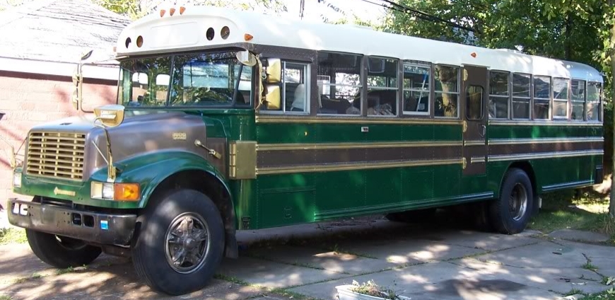
I also got an additional attaching post for the camera, as the suction cup mount (which holds really well, BTW) is angled, and I was hoping to run the camera from the upper dome window where I had the ‘School Bus’ sign removed and replaced with glass.  I was able to test it in that window, angling the camera as high as the mount would allow (in the video below).  The additional post can be mounted to a flat surface (like a an overhanging board or windowframe molding) and allow the camera to be likewise flat.

So, what follows is a video, as I’ve just learned how to do the basic editing to stitch the videos together.  While I could have set the cam to record it all as one file, I’ve done enough computer work to know that data can get corrupted, and I like the security of multiple files.  The G1W-C allows for multiple settings of file length, and I chose the 5 minute one, which limits the file length to that, then starts a new one.  An interesting feature of this is that the files can’t just be stitched together, as they overlap each other by 1 second, giving a bit of extra security in case one glitches somewhat.

One downside of the cam is that I apparently left it unused for too long before this trip.  While I really like the on-screen documentation of the time/date, it resets if you don’t power it often enough, and as I was in a bit of a hurry to get going, I didn’t double-check it before we started off.  And what you’ll see behind the time-stamp is a nice hour-long trip from Buffalo’s streets to the tranquil and relaxing Sprague Brook Park, on a mostly sunny day that does a nice job working the adaptive intensity circuits .  And if you look closely, you might note my passenger, Aaron, in some of the odd reflections in the window.

So let me know what you think.  Is this too hard to watch with the center of vision pointing at the road, rather than the horizon?  If I tilted the camera up higher and the nose of the bus was out of frame, would that be too disorienting?  Should I just move the camera down to the windshield and mount the flat mount on the underside of the metal ‘shelf’? So many options.

(And if you can’t see the video in the post, it’s on youtube.)

I let the magic smoke out of a wire *or* the Magic Door (Linear Actuator, Part 2)

So you might remember that when I put in the linear actuator for the door it had a handy remote that could easily both open and close the door.  Now, as much as the remote controller unit was a black box, its exterior functions were really simple – the two wires for one channel either are pos/neg to open or neg/pos to close, thus sending the 12 VDC through the linear actuator’s motor one way or the other to get the desired result.

And, in understanding that, I had thought that I could just put a DTDP switch in place and be able to electronically open and close the door with the switch.  My thought was that I would use the positive power and ground that the controller was hooked to, and that way, the circuit would connect in parallel to the linear actuator’s wires, but bypass the controller entirely, and all would be good.

It was easy enough to hook up, and after double checking the circuit, I tested it.  The door was closed, and I flipped the switch, and the actuator whirred and the door opened, leaving me happy, until I flipped the switch back and as the door started to close, one of the wires from the controller to the linear actuator let out all its magic smoke as the insulation melted away.  I quickly flipped the switch off and examined the system.  All was as it should have been, the polarity to the linear actuator just being put to the opposite wires.

A quick check on the remote showed that the controller unit was still clicking along with the use of the remote’s buttons, but the wire was fried, and the linear actuator wasn’t working.  As I needed to clean up the bus to move it, I quickly disconnected the switch, cut out the damaged wire and spliced the ends.  The controller clicked but again the actuator didn’t twitch.

I tested the actuator wires by making a circuit to the positive and ground, and the actuator slide the door closed, much to my relief.  And then I decided to test out the second channel of the remote.  I quickly wired it to the actuator (with no additional switch in the circuit), and tested it out with the remote.  Again to my relief, the door opened, and then closed again with the remote.  So the system worked, and I buttoned it all up.

So now I’m left with a DTDP switch, which I think may end up running some lights, a controller board that (I discovered after the fact) needs a new wire soldered to it so the first channel will be usable again, and a quandary about why one wire of the controller shorted the circuit while the other didn’t.  But, the door still works with the remote, which is the important part.

Testing out the Backup Camera(s) (Part II, The Testing)

(Continued from Part I)

So with the cameras and the screen, I was ready to test them out. The screen was easy, as it had its own AC adapter.  I was able to just plug it in and it came right on, gave a nice blue screen indicating that it was set for the VGA input, and after 10-15 seconds of finding no signal, it went to sleep.

I could wake it easily by either selecting a new input (VGA->Cam 1->Cam-2->VGA cycle), or by just hitting the power button, but with no input, it just went back to sleep again.

The screen with a real image!

I have a mini-HDMI->VGA adapter for my tablet, but that didn’t work to give a testable signal, so I had to go hook it up to an old XP box.  The booklet manual said that the optimal resolution was 800×400, but the computer’s resolution wouldn’t go down that low.  At the lowest setting though, it was pretty easy to see.

Tiny little icons at higher resolution on the graphics card.

Putting it back up to some 1100×800 dpi (the computer’s regular output setting), the image was still pretty clear, but the text and icons got really small.  I’ll have to play with the setting once I get the bus’ computer up and running.

But with proof positive that the screen was in good shape, I went to checking out the cameras.  The little, cheap camera just had the red and black wires for power, so rigged a plug using a female four-pin power connector from an old computer fan, and hooking it up to an adapter that was meant to power a hard drive. With the VGA connected to the screen, and a button push to cycle camera 1’s input I got … a black screen.

A little clarification.

At first I checked all my connections, then realized that if I cycled the input again to camera 2, I got a picture. One Sharpie later, I had that system all worked out, and went about trying to get a nice image I could photograph easily, but found that it wasn’t easy to get what I wanted because the picture was, indeed, mirrored (just like I knew it would be but my hands still wanted to turn it the other way).

The little, cheap camera`s eye view.

One of the other issues that people complained about was the guidance lines.  In looking at the view, I don’t see them being very intrusive.  I can, however, see how they form a great fixed reference point for backing up.  For this picture, the camera was at couch height, and the distance to the far wall is ~21 feet.

I hooked the other camera up to the same power source, and put it in a similar placement (just next to the first camera).

The bigger back-up camera's view.
The bigger back-up camera’s view.

The lines are more pronounced on this camera, but they are more colorful.  The back wall here looks closer, but you can see less of the walls, even though the two cameras were at the same distance.

In recognizing this, the cheaper camera has a much greater field of view, but with much more distortion.  At the time, I just noted it, but in thinking about it since then, it seems that this difference will actually help me with placing the cameras on the bus.

But there was another thing to test with the more expensive camera, and that was the IR LEDs.  For that, it was an easy thing, as the photosensor that turns the LEDs on doesn’t need complete darkness – even a good shadow would do it.  So for that, I just held the camera up off the couch (looking at the couch), and lowered it until the LEDs kicked on.

No IR LEDs on ...
No IR LEDs on …
... and with the IR LEDs on.
… and with the IR LEDs on.

The ‘night vision’ works fine, though the bright ‘light’ of the LEDs washes out the colors.  But really, when I’m backing up at night, I think the color of the object I’m getting too close to is less important than if I can see it clearly.

So my plan is now to mount the small, cheap camera up high on the bus (there’s a bevel right above the back dome window and below the clearance lamps that should put it at a great angle), and use it as a regular rear view mirror, displayed on the screen during normal driving operation.  I’ll get a nice view of what traffic is right behind the bus, and a nice wide angle on the sides.  The other camera looks like it will need to be pretty close to the ground for the LEDs to have a good effect, so I’m going to play around with mounting it under or just above the back bumper.  Since I can change between the two views with just a click of the cycling button on the screen, I should be able to get both a ‘big picture’ and then a more detailed view when backing in somewhere.

I’ll post again for on-the bus placement testing and installation …