Tag Archives: AC Electrical

The Norcold Refrigerator 876EG2 *or* Electrics (Part III)

After getting the AC breaker box and converter installed and working, I set about getting our fridge in place and powered.  The 4-4 1/2 cubic foot fridge that we salvaged from our friends’ trailer was what we wanted in terms of a small three-way unit, but unfortunately, it didn’t work.  First, the controller card wasn’t responding, and even though the ammonia system was sealed and I could force the AC heating element to fire up and run, the fridge just wouldn’t cool.

Now, if you’re only used to our modern, AC, compressor refrigeration systems, the ammonia-based systems of a heat-powered system may seem odd. But they are super-quiet (aside from the occasional gurgle) and great for boondocking.

Here’s a nice introductory video on non-mechanical refrigeration systems:

If watching the video is too long for you, essentially the three-way (two electric heating elements or the LP gas heater) system works non-mechanically (no compressor to force-chill the liquid/gas coolant) to cool the interior of the freezer and fridge through heating ammonia to a gas, then taking advantage of the fact that it will condense back to a liquid and the chilled liquid ammonia will become the cooling factor for the freezer and the fridge.   Ammonia boils (and thus condenses back to liquid) at -28°F, which is more than enough to keep things freezing in the freezer.

Now, in getting a second-hand non-mechanical fridge system, there are some trouble-shooting things you need to do, unless the owner you’re getting it from can demonstrate that it definitively works.  One is to tip it on it’s back for several hours, then raise it up slowly.  This is done as an attempt to insure that all the liquids are back down in the reservoir so that the ammonia can be boiled off, and thus cool the interior of the fridge/freezer.  The other is to bypass the thermostat’s circuit board and put a heat source (like the electric heater that is installed on the unit or an LP source, like a low flame propane torch) to see if the ammonia will boil out and chill the system.

The most important part of the system is the cooling system, and many old fridges can be rehabbed by purchasing a new cooling system (most for around couple hundred dollars).  After I tested the salvaged unit for a couple of days and found no temperature change in the interior at all, I considered this, and started in to do my research, finding out that the shipping charges for these rebuilt/recharged systems can be costly.

It turned out that for us that a (relatively) local seller on Craigslist was selling a 6 cu ft Norcold Refrigerator (model 876 EG2) for about what it would cost for us to get the rehabbed cooling unit for the smaller salvaged unit.  And, the seller had it running and cooling when I came to pick it up, so I knew that it was good.  (He was also the one that threw the converter in for a song.)  This was a good deal, as a comparable new unit like one of these is much more expensive:   

The 876 model is a two-door unit, which was a change from the salvaged one, which had a small metal enclosure for the freezer that helped to cool the rest of the fridge.

The two door unit makes for a much more energy efficient and manageable freezer and fridge in terms of temperature.  You don’t get ice in the fridge area and the freezer stays really cold.

However, the 876 is taller and slightly deeper than the salvaged unit, which threw a bit of a wrench into my plans.  As you might remember from my floorplan, FloorPlans2 there was a covered window behind the fridge, as the fridge needed air space for the cooling vents, and for the heat and exhaust to be vented  outside in order to function.  One of the major reasons why absorption refrigerators don’t work has to do with insufficient ventilation and blockages in the heating system.

With the smaller, salvaged fridge, I had expected to cut vents into the skinned window and not have to cut the roof, even with the fridge sitting up over the wheelwell (I had expected to use the seat-rail as a support).  However, with the much larger 876, I would have to cut off the seat-rail, and rebuild the wheelwell cover in order to lower the fridge as much as possible, and then cut a vent hole in the roof.  I had also planned to cut vent holes in the floor to gain air flow and O2 for the LP burner, but with the depth and base construction of the 876, I wasn’t able to do that, so I would have to also cut into more of the skin of the bus in order to get good air flow (and I was nervous about both of these cuts, since I hadn’t done anything to the exterior up to this point!).

Now, I knew that the fridge cooled nicely on 12 VDC, and wanted to verify that it would run well on AC, and was upset when I plugged it in and got no response! But that was because the thermostat circuitry is all 12 VDC, and must have power to run so the AC can kick on the heating element.  Once that was rectified, I confirmed that the fridge would automatically switch from a DC source to an AC source (and back) when the AC was available for the heating element.  This is kind of a big deal as the electric heating elements are not as efficient as the LP burner, and when available, shore power is your friend for cooling.  The DC power is important for while you’re driving (and perhaps for regular running when all the solar panels get installed), and the LP is good for extended boondocking.

But before I could check and see if the LP worked, I had to replace the gas line from the solenoid and, as it turned out in dis-assembly and cleaning, a new burner.  The new burner was easily available  (though it used to cost less than it does now!) and needed a new compression fitting at the end of the tubing.

Luckily, I had bought a really nice set of tools for flaring compression fittings to redo the brake lines in my wife’s Daewoo, and it turned out that the gas line was a 5/16″ line that I had a bunch of, so I cut and formed up a new line that sealed up nice and tight, and all worked well.

Unfortunately, as the 876 had been pulled from an RV that had been sitting unused, it was from a unit that had been built in the late 80’s or early 90’s, and had this horrible beige padded covering that stuck out and made the fridge even that much bigger.  I had examined the doors and found that the hinges could not only be moved to the right side (from the left where they had been), but also that with the removal of one of the edges the padded facing could be easily removed and replaced with some stained oak plywood, which fit a lot better with our overall look.

I trimmed the existing wheelwell covering and removed the pieces that held it up.  Some 2×3’s built up a new floor for the fridge and then I could measure for the area that it would need for the air venting intake and then the hot air exhaust.  These presented some problem as the opening I wanted to cut would have gone right through one of the rub-rails.  I wanted to preserve these as much as possible so that the bus would keep as much of it’s structural integrity as possible.

To deal with this, I cut the skin between the rub rails to get the opening necessary for the air flow.  This was reckoned from the venting salvaged from the old trailer.  I ended up cutting down the locking casing for the smaller area so that I could get in and clean out the burner, then cut the vents so that the upper area could be screwed in place and sealed.  This makes it removable if necessary, but not with the ease of access of the lower area, yet also keeps the rub-rails intact.

For the top, I, with no small amount of trepidation, cut into the roof.  Three cuts allowed the roof to spring up above the reinforcing plates inside, and two triangular metal pieces for the sides created a nice opening for the heat to exit the bus and create a nice draft to pull cool air over the cooling fins of the fridge.  It has window screen over it to keep insects out, and will (eventually) get a nice sheet metal cover to keep the rain out.

Inside, the air was channeled to the outside by some wooden ducting, sealed with weatherstripping and screwed in place.  The actual flue from the LP burner would run up against the metal, keeping the burning hazard at a minimum, and allowing for plenty of air movement.

Wires were run for the DC and AC power sources and the fridge now runs like a top, even bringing some pop-ice sticks to a frozen state within a few hours.
Problems with getting things done on the bus …

Every job has its problems.  Some of those on the bus are relatively simple to deal with, like the curved roofline.  To combat that, I made up a template using one of the interior endcaps and some sturdy MDF.  Voila, I can now cut a curve for wall paneling or shelf ends that will fit any section of the interior roof to a shape that will fit pretty well.

But some things are bigger problems.  Like in working on the electrical system, I’m up to the point in blogging where I *should* be installing the DC Circuit Breaker box.  It’s a wonderful thing from Blue Sea marine rated so it’s good with moisture, separate wiring for backlighting, and available in 12 or 24 volts, and you can have all the breakers wired to one power source, or source them separately (which is what I’ll do).  

But I can’t put that in the system yet.

Why, you ask?  Because it has a cascade of other jobs that need to be done before I can get there, each job hinging on the one before it.  The circuit breaker job, for example, needs to have paneling up before it can be installed in place.

Now, I’ve been doing some nice flat panel oak wainscoting on the walls, and was planing on doing more of it for the area behind the captain’s chair, so it would need to be built to fit around the existing electrical outlet, captain’s chair back, & AC breaker box.

Oh, and around the housing for the electrical panel and  bus wiring that’s just to the port side of the captain’s chair.  Under the plastic there’s lots of empty space and I need to decide how much needs to be taken up with what and how best I’ll get access to the wiring that will still reside in there.

And of course, I have to build the paneling and enclosure around the vents for the defroster (by the port window) and the vents down by the floor for the driver’s heater outlet.  Oh, and the control for the heater core fluid flow.

Unlike modern school buses that have a dial like your car that opens and closes a vent that allows air to flow through or around the heating core (a miniature radiator), our bus has a 1/4 turn valve that allows or restricts (or stops) the hot coolant from flowing into the core, which is mounted just under the big panel of toggles and switches.  Unfortunately, it’s a little thing with short wings, and is really difficult to turn on or off while driving.  As such, I have the body for an old ratchet that I need to weld to the valve  for better control.  And this needs to be built into the paneling in such a way that the hardware of the valve can be attached to the back so it doesn’t move about.

But before I can get to working on this paneling, I need to deal with the floor.  I took apart all the original floor up to the captain’s chair and replaced it with batten strips, insulation, and plywood underlayment. But the floor fore of that, is still the old rubber and marine-grade plywood.

Which is held in place in the front with metal plates. And there’s also a big plate that covers the opening over the transmission for the shift lever to come through, with a nice rubber boot to seal it all up.  And, of course, the plate needs to come up so that the floor can be replaced.  But to take the plate up, the boot needs to come all the way up the lever and off over the shifter knob.

Said shifter knob needs to be removed so the boot can come off the lever, but has (so far) resisted all my attempts to unscrew it.

And then, last but not least, is the captain’s chair itself.  The chair has six bolts holding it down, and the seat belt is held down by two more bolts.  While these really shouldn’t be a problem , there’s a more complex chassis configuration in this area, and it’s rather hard to get to some of the bolts from underneath.  And I’ll actually have to drill up through the new floor in order to put new bolts in the right places to reseat the chair and seat belt hardware.

All to install a DC circuit breaker box …

(That said, I will be getting things done …)


Electrics (Part I)

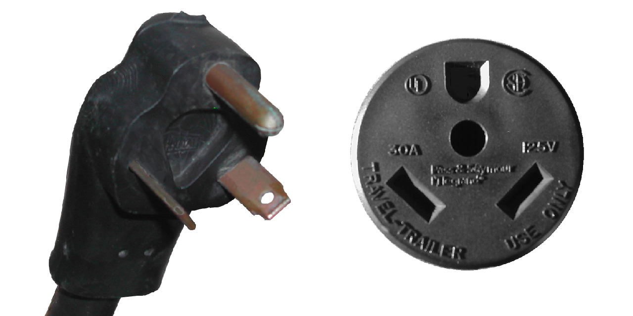
After the air system was in, and I knew the locations of the air lines and accouterments, I could run the electrical lines.  A good friend of ours had let us salvage parts from a 1970’s vintage RV trailer, and from that I was able to get some electrical components,   the two important ones for this were the 10 gauge 25′ power cord and the 30 amp circuit breaker box.  The box had a 30 amp main switch, and three additional 20 amp breakers.  The only odd thing was that the 30 amp plug

A 30 Amp plug

on the end of the power cord had been replaced with a 15/20 amp plug meaning that the power coming into the bus was limited to 20 amps (so far).

15/20 Amp plug

One of the critical things that I learned on our Sprague Brook trip is that getting the power inside the bus proper is very important.  And having a roll of 25′ of three-ply 10 gauge stranded wire to connect to a power outlet outside the bus is no small thing to mount in a secure location.

I decided that the wire would coil in the empty area of the battery box on the port side of the bus, and thus would have to come up through the floor just by the heater box inside the bus compartment (right by the captain’s chair).  As with the soft air line, this needed to be protected from the sharp edge of the metal floor, where the vibration and movement of the floor while the bus is in motion could cut the insulation and wires, producing a dangerous short or a ‘hot skin’ condition of the bus, which is where the metal skin and frame carry the 120 volt AC current, and anyone touching it completes the circuit (Zap!).

I wanted to keep the 10 gauge wire, though, as the smaller the gauge, the less electrical energy is lost getting from the plug to the outlet, and it turned out that the ~1/2″ cable fit just inside a 3/4″ compression connector (for an electrical box to connect to a rigid chase pipe) that I had acquired as a “bit”.  once I had double checked that the hole I was going to drill would come out in the battery box, I slid the compression connector down into the hole and screwed it down tight (leaving the unneeded compression fitting off), and it produced a perfect safety barrier against the sheet metal flooring.

Looking into the battery box, the connector is on the top and the cable coming down through the floor.

After the connector was fitted, I ran the wire through it, attached a new 15/20 amp plug, and then set up the breaker box.  I decided to put it just behind the captain’s chair, as it wouldn’t be of any use while the bus was in motion, and was conveniently located by the battery box and the seat where I would be storing the house batteries.

The breaker box in place in the frame of the wall between the captain's chair and the rear-facing bench seat in the passenger area.
The breaker box in place in the frame of the wall between the captain’s chair and the rear-facing bench seat in the passenger area.

The box has a 30 amp main, and three 20 amp feed breakers.  I attached the power cable to the main, and ran one of the 20 amp breakers to outlets behind the captain’s chair and another in the ‘closet’ area behind the wet-wall for the bathroom.

The specs on the power converter.

Another of the breakers was dedicated to a Magnatek Model 3240 power converter.  This is a unit that takes 120 volt AC  input and converts it to 12 volt DC current.  it can be hooked up to 12 volt batteries and has an automatic switch to detect the AC power, and switch to battery power when the AC is disconnected, and vice versa, without cutting power to the attached 12 volt appliances.

The power converter in place behind the rear-facing bench seat, attached and double-grounded against the wall.

I had picked this up when I got our fridge (a forthcoming post) and the guy threw it in for a very small amount, which on the one hand is great, since we needed something like this, and on the other hand is annoying, since it was an ‘as is’ purchase and it turned out the battery charging element wasn’t working.    At any rate, the converter is a simple affair, using regular automotive ‘knife-style’ fuses, and having both filtered and unfiltered DC outputs (filtered is for sensitive electronics, like the radio).  One of these I set up to go to the radio/tape deck, so that the clock would stay running and I could listen to music while the bus wasn’t on, and another I would run off to the DC connection for the fridge.  Others would be for lighting and appliances like the water pump and water heater, but those will come later and be run through a DC breaker box which isn’t in place yet.

More on this in Electrics (Part II)