Air (Part II)

Now, to run this from the tank below the floor up through the bus body and out to the horns needed some other bits to work correctly.  First was to put in a pressure regulator, which by adjusting the dial could throttle the pressure to any desired between zero and 200 psi, or however much was in the system.

Pressure Regulator
Pressure Regulator

This was an important consideration that many of the ‘air horn kits’ that I found on-line lacked, as it allows you to quiet your air horns/chimes while you’re in an area with people out and about, rather than a highway with people in vehicles.  While there are people who seem to delight in scaring people with a sudden blast of sound from an air horn at maximum pressure, this is horribly irresponsible and potentially dangerous.

As the regulator had not only a 1/2“ through port, but also two 1/4“ regulated out ports, I decided to use one of these to run to a pressure gauge that I could mount on the control panel.  For this I used mainly a ‘soft’ line of a tough plastic with a 3/8“ interior dimension (but was marketed as a 1/2“ air line), which was not great at turning corners, kinking easily, and causing me to use hard 90 degree elbows to make corners.  This was a great way to check what the pressure is in the auxiliary tank, but had the drawback in that when you dial back the regulator to quiet the horn/chime, you only see the regulated pressure, not the whole tank pressure.  However, as the regulator dial is mounted behind the driver’s seat, this regulated gauge allows you to change the pressure without looking back for too long while driving.  The gauge itself had threads that were just the size of a removed switch cap on the control panel, so the installation was relatively easy, despite having to route the line between all the other lights and switches on the panel.

'Soft' air lines, 1/2" ID in the box and the 3/8" ID around the outside ...
‘Soft’ air lines, 1/2″ ID in the box and the 3/8″ ID around the outside …

The next step after this was to install control valves to actually work the horns.  While some people on-line suggested using simple ball valves for natural gas/LP lines, these don’t automatically close, which poses an additional distraction while driving, as opposed to spring-loaded, normally closed valves.  I got two non-stepped valves, which are amazingly heavy-duty.  Stepped valves have three settings (closed, partly open, and full open), while non-stepped run from closed to full open and all the range in-between depending on how hard you pull on the handle.

Non-stepped control valves

To counter the possible torque of pulling on one of the handles energetically during a tense moment, I ended up deciding to use hard lines from the regulator to the valves, which made things a bit easier as I needed to split the air line to get to both of the valves.

The lines for the air horns was 1/2” (ID) line to supply the volume of air needed to sound the horn, which can drain the 20 gallon tank fairly quickly, and the hard line was constructed from ‘black’ pipe and brass fittings, and used Teflon tape to seal the threads.

Showing the hard lines from the pressure regulator to the valves mounted on the shelf to the port side of the captain's chair.
Showing the hard lines from the pressure regulator to the valves mounted on the shelf to the port side of the captain’s chair.

These were attached to the shelf that I ended up constructing just above the captain’s chair on the port side, giving easy access to the valve handles, while also not blocking the view.  I had expected to put a couple of hanging lines on the handles (like the old truckers had), but the valves ended up being so low and handy that I decided against it.

Another view of the hard lines and valves without so much backlighting.

While I went with hard lines from the pressure regulator to the valves, most all of the rest of the line was ‘soft’, a thick, durable air brake line of woven fiber and rubber that could be bent into tight angles without crimping or binding.  This allowed for some flexibility of where to run the lines and to easily get the air to a horn along the curved roof.  However, it did pose one problem; that of how to run the soft line through the flooring, which was a 20 gauge steel sheet.

The nice bright dot (of the bright driveway) is  where the air line will come up
The nice bright dot (of the bright driveway) is where the air line will come up

I got around this by using a short ‘hard’ pipe through the floor with flared barbs at each end to attach the pipe and the ‘soft’ line.

A brass barb fitting on a black iron pipe to go through the floor


A dark photo of the connection between the tank and the 'through-the-floor' fitting
A dark photo of the connection between the tank and the ‘through-the-floor’ fitting

The first air sounding unit I put in was the air chime.  Nicely finished with brass, I wanted to install it with the pipes pointing up, but due to the construction of the lower ‘bell’ housing not having any drainage hole for rainwater, if I had, the air line down to the valve would fill with water and a winter freeze would have been disastrous.  So, it got mounted sideways, which still isn’t bad.  I ran the holes through one of the plates that I put over the school bus flashers, and piped a hard, brass air line in through the steel.  The mounting for this was simple, as the chime had three threaded holes to secure it, so once the exterior of the holes had been ringed with butyl sealant, it went together easily and securely.

4 Note Air Chime, Brass (From raneystruckparts.com)

That said, a word of advice to people who might be considering doing something like this – be careful with your bolts after getting things in place.  The butyl sticks to everything, including bolt threads, and can make it tough to get things aligned.

But it certainly can be worth it, as shown by the finished chime, in place:

The air chime in place above the driver's eyebrow
The air chime in place above the driver’s eyebrow

To be continued (in Part III) …

Air (Part I)

One of the nice things about the bus is that it has an air system for the air brakes, which means that it has a compressor that runs off the engine with a mechanical pressure regulator and a dehydrator for the system, which doesn’t mean that it makes apple chips, but rather that it helps keep water from building up in the brake lines (which can be a big deal in the winter!). You might ask why this is a nice thing, since your car most likely gets along fine without such things.

Well, first, it offers the possibility of refilling tires if need be, or, if you like, any number of air-powered accessories, like tools (impact hammers/wrenches, drills, jacks, etc.), or an ‘air seat’ for the driver (highly over-rated from my experience on school buses that have them), or air suspension bags (to aid the shocks and smooth the ride), or to run air horns. However, one of the things that our bus didn’t have as part of its air system was an auxiliary tank.

Air brakes for a single unit vehicle only need one tank with three partitions. The first partition (wet tank) is the place where air is stored for future use, and to trap more of the moisture that might have made it through the dehydrator. The second partition feeds from the first tank and serves to provide air to the front brakes, and the third (also fed from the first) provides the air for the rear brakes. This is why, on a vehicle with air brakes, there are either two pressure gauges (one each for the second and third partitions) or a single pressure gauge with two differently colored needles, each indicating one of the two brake partitions. (Multi-unit vehicles with air brakes usually have a separate gauge for the trailer brake tanks.)

Now, some of the people on the Skoolie board had just tapped into the first tank for a ‘service’ air line for tools (or in a pinch, to hook a compressor to, in case the one on the engine failed), but it’s not something to tamper with if you want safe brakes. I wanted to be able to use an air line for tools, as well as run air horns, and have the possibility to upgrade to air suspension bags in the future if we decided we wanted it. In order to do this, we needed an auxiliary tank.

I found an auxiliary tank online that was a 20 gallon one that would fit alongside the air brake tank under the bus. While one might think that this would be a simple matter of running a line between that first partition of the brake tank over to the auxiliary tank, you can’t do that, because there is a maximum amount of time your air brake system can take to get up to “working pressure” of about 85 psi from starting with no pressure. If you hook a 20 gallon tank up to that first partition, you have to bring that whole storage area up to the 85 psi threshold within that minimum time, which just doesn’t work.

Air pressure valve, 85 psi on

In order to get around this problem, I had to install a pressure valve in the line between the two tanks. This valve stays closed until the pressure in the brake tank partitions get up to about 90 psi, then opens, allowing the compressor’s air after that bring the whole system up to pressure over a longer period of time. One of the things that ends up happening here is that I have a lot more air available for my brakes when the system is up to pressure (120 psi), as the 20 gallon tank can feed air back to the brake tank as long as the system pressure is over 85 psi.

The pressure tank I got had a whole lot of ports, but none on what I wanted as the bottom (because of the placement of the ‘feet’ for attaching it), and one on what I wanted as the top, so I ended up having to support it from underneath, rather than bolting it directly to the floor. The location of this port to be facing down was important so that it could be used as a drain to get rid of excess moisture, and I did double-duty in putting in a pressure release valve in, so if the system over-pressured (150 psi +), it would let the excess pressure out and save other elements from stress. , but I could also manually activate it as a drain.

Bedrails can make good structural supports!
Building supports for the air tank

So, one port was the pressure relief valve, another was the air coming in from the brake tank, and, for now, only one port would be used for feeding up through the bus body to two air sounding devices. The first was a Leslie Supertyfon RS-3L that was originally installed on a Conrail Diesel locomotive that my father had acquired somewhere (more on this later). The other was an ‘air chime’ which, when used nautically ends up meaning an air horn, but in this case was the closest I could get to a steam whistle. It channels the compressed air through four different chime pipes, a rich sound compared to the air horn.

The next thing to do was to lift the tank into place, which is actually tougher than it sounds, as I was attaching it to the bottom of the floor and to the side of the bus’ ‘skin’ where it drops down.  In order to hold the tank in place, I decided to use a nice floor-jack and lift it, but this also was trickier than it sounds, as the tank was balanced just so and having the supports catch on the brake tank or the skin of the bus could cause it to tilt and slide off the jack.

Jacking the tank into place
Lifting the tank into place


The new tank and pressure regulator in place


To be continued (in Part II) …


And for a really nicely detailed explanation of air brake systems, look to this great Army informational film from 1967:

https://www.youtube.com/watch?v=42u4v-AbWA4

Buses and fuel

  On a bus-conversion board, I found a discussion on fuel tanks. Some buses have one, and reports of size varied from 40-100 gallons. Some buses come with two (seemingly of the same size) which vary from 30-100 gallons.  (It would be awesome to have two 100 gallon tanks … As it is, we have a 60 gallon tank.)  But perhaps more important for how far you can get on your tank(s) of fuel is your miles per gallon (mpg).
  As for mpg, actual mileage of fully converted buses (that people have reported) go from 3-16 or so (diesel).  Much of this seems to hinge on gearing and travel speed, but some is in the styles of buses, with ‘conventional’ or ‘long-nose’ chassis get better mpg than the ‘pushers’, which isn’t a surprise, as the nose is more aerodynamic than the ‘flat wall’ of the buses with the rear engine.  Even with the aerodynamic issues, buses lose out in mpg because, as Mr. Jake von Slattso nicely puts it, they’re steel skin over steel supports with more steel inside, all mounted on a true medium truck chassis. Plenty heavy, but plenty safe , and with lots of space. Ours, even with the low amount of travel it gets and the much higher amount of idling is getting about 12 mpg.
  In comparison, while most factory-made RVs are on lowered chassis to optimize head-space, and are built of wood, fiberglass, aluminum, and sometimes steel in order to reduce weight, they still seem to get between 2-16 mpg (diesel), with some of the newer hybrid engines hitting on that upper range.  But the structural stability of these is nowhere near that of a bus, and that is not even factoring in the large slide-outs that compromise the structure as well.
  So, when asked about (or confronted with a) “well, wouldn’t it make more sense to just buy an RV for better mileage?” or “don’t forget that all that weight you’re adding in tanks/walls/appliances/frippery will take away from your mileage!”, I have to take a deep breath and re-iterate that school buses are about the safest vehicles on the road.  And yes, while a lightly (or under-) loaded vehicle is likely to get better mileage than one that’s fully loaded, buses with air brakes stop better when loaded, and most buses are geared low enough that the added weight really doesn’t stress the engine too much. (One guy on the Skoolie board commented that he built Jacuzzis into his buses and the mileage didn’t vary at all whether the 8/10-person Jacuzzis were full of water or empty.
  We’re been exploring WVO (Waste Vegetable Oil) as a fuel source, in order to make the project more efficient in its mileage. Why WVO, you might ask? Well, most diesel engines will run on it with -no- modifications whatsoever (Apparently, there’s a type of fuel-lubricated rotary fuel pump on some engines that has an issue because the WVO is more viscous than diesel fuel). Major costs involved in the conversion are auxiliary fuel tanks, a fuel tank heater (WVO needs to be at about 160 degrees to flow like cold diesel), a flow switch/ electric valve and possibly new, corrosion-resistant fuel lines.
  There is a filtering/ settling process to actually get the WVO to be usable (though some don’t worry about this – which may or may not damage the injectors), but you end up with a cleaner burning fuel that smells like french fries (or probably in our case, wings).  There’s an outfit in Mississauga, Ontario that makes in-line pressure-driven centrifuges that would take water and particulates out of the WVO.
  I’ve asked on another board how the mileage with WVO compares with diesel, and it seems like WVO should give about 80% the power of diesel.  I’ve been toying with getting another tank to get 50-100 gallons worth of travel of our trips for just the labor and filters of processing out the sludge from the WVO – which will likely be well worth the savings at the pump, since many restaurants have to -pay- to have the stuff disposed of …

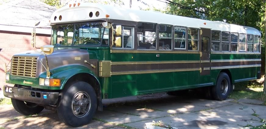
Rebuilding a school bus into a rolling house.